
Turn
Signals
Turn
Signals
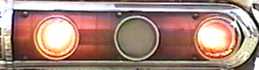
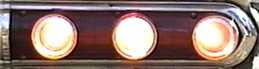
I've always loved the sequential turn signals on old T-Birds and Cougars. I've wanted to build my own sequential turn signals for a long time but until I got my 202 I never had a car with three tail light bulbs on each side. Actually my Comet only has two tail light bulbs from the factory but with new sockets the backup lights can be used as additional tail lights. Backup lights were optional in '64 so a tail light lens without the backup light is available. The backup light is a circle between the two tail lights. My cousin told me I should isolate the tail lights to the circles so they would match the backup light. What a great idea, the three dots look much better and more balanced than the factory tail lights. Soda cans are perfect for the dividers. They are the right diameter, easy to work with and the insides are shiny to reflect the light. I cut some 3.5" tall cylinders and stuck them behind the tail light lenses. I traded an intake manifold for a set of lenses without the backup lights. The auto parts store had a dual element socket that was a direct replacement for the single element used for the back up lights. Converting the tail lights to use three bulbs was a lot easier than I thought it would be. Which is good because making them blink in sequence turned out to be harder than anticipated.
 After
After
The sequence control is simple. Two controls
are needed, one for the left and one for the right. The inside lights are hooked up the
same as a standard turn signal. The middle and outside lights are connected to the control unit. All the
control does is delay the lights. Both the middle and outside lights are triggered by the
inside light and work independently from each other. The control is reset when the lights
go off. The brake lights use the same bulbs as the turn signals so the brake lights will
sequence once then all the bulbs will stay on until you let off the brakes. Unless one of
the turn signals is on then one side will continually sequence and the other will stay on.
The controls can be wired so the brake lights don't sequence if that is what you wanted.
To build my controls I used a standard 556 dual timer to actuate a couple relays. Instead
of fixed resisters I used trim pots so I could easily adjust the delays with the controls
in the car. Be sure the relays can handle at least 2 amps a piece.
I installed the controls but the flasher was too fast. The controls
only turn on the lights, the flasher under the dash is what turns them off. The flasher
needs to stay on long enough for all three bulbs to come on. I decided to build my own
flasher so I could adjust both the on and off time. I wanted it to stay on three times as
long as a standard flasher but stay off the same amount of time. My first design was a
horrible failure. The second worked but was erratic and I couldn't adjust it the way I
wanted. The final design works great and uses
fewer parts than the others. The on time is adjusted by changing the 10k resister and the
off time is adjusted by changing the 47k resister. After spending almost a week building
my own flasher I found out a standard flasher can be adjusted. Check it out,
this is something you won't find in any shop manual.
With all the lights flashing the way I wanted I only had one more issue
to resolve. With all the bulbs lit the turn signals weren't much brighter than the tail
lights. The factory only used 18 gauge wire to the turn signals. With all the bulbs and
control on, each side pulls about 7 amps. I was losing about 4 volts. Not only do dim
lights look bad but it is a clear sign the circuit is overloaded. I decided to run a big
wire straight to the turn signals from the battery with a relay for each side. I used 8 gauge wire run to a pair of 30 amp
relays because bigger is always better. I put a 20 amp circuit breaker up by the battery
just to be safe. Now it only loses two tenths of a volt and pulls less than an amp through
the factory wiring. The turn signals and brake lights are extremely bright now. Check out
my turn signals in action.
A quick note on wiring. Crimp on wire ends are quick and easy to use
but will come loose, oxidize, and eventually fail. To make the wire ends last longer you
should remove the plastic insulator if it has one, crimp to the wire, solder, then
insulate with heat shrink tubing. You will need a big solder gun to get the connector and
wire hot enough to solder. I use a 200 watt gun. It takes a bit longer to solder and heat
shrink but you will get a solid connection that will last forever.
If you have any questions or comments please e-mail me at mrriggs@gofastforless.com.
Update: 7-14-2005 - The dead link above was to another web page. I have never done the mod but I'll do my best to explain it. Basically you just crack open the flasher and bend an arm to increase the point gap. To get it open you carefully pry back the metal cover where it has been bent over the base plate. Once it is open you can plug it back in and turn on the blinkers. You will see how the thing works. A spring heats up and bends which breaks the circuit, when the spring cools it goes back and completes the circuit again. You should see an arm that you can bend out to increase the gap, the larger the gap the slower it will go. Handle it carefully as parts of it do get hot. You should be able to bend the arm with it working so you can see and hear the change as you are working. Once you have it where you want it then glue the cover back on.